Hello all!
It all started the night before Thanksgiving. It was 11:58 PM, and I was up late doing pretty much nothing when I had an idea… “What if I build a robot to pass food around the table?” So I stayed up all night long to build it, which in reality took me around 2 total hours, and the other 8 were spent dozing in and out because staying up was a terrible idea like this entire thing was.
The plan was simple: use 2 motors with 3D printed brackets, a paper plate, an Arduino Nano, and an ultrasonic sensor to make a robot that moves around the table. When the robots distance to an object in front of it is greater than 5 centimeters, but less than 150 centimeters, it will move forwards until it is less than 5, at which point it will stop moving and wait 30 seconds before turning. If the distance is greater than 150 cm it will also turn, as this generally assumes that it has reached the edge of the table and it may fall, so it will turn away from it.
Arduino is written in C++, so there are 2 main functions in the code, as well as the ability to declare global variables outside of these functions. We will begin by declaring variables that hold the values for which pins we want to use as our motor outputs, our ultrasonic sensor input and output, include the ultrasonic sensor library, and instantiate the ultrasonic sensor.
#include <HCSR04.h>
int triggerPin = 6;
int echoPin = 7;
#define m1low 2
#define m1high 3
#define m2low 4
#define m2high 5

UltraSonicDistanceSensor distanceSensor(triggerPin, echoPin);

// M1 is motor 1, which is on the left side
// M2 is motor 2, which is on the right side
The next function is called the setup function, which is generally used to instantiate classes and setup things like serial monitors. In our case, we are using it to assign the pinModes for our different input and output pins, as well as set up a serial connection for the ultrasonic sensor.
void setup() {
  Serial.begin(9600);
  pinMode(m1low, OUTPUT);
  pinMode(m1high, OUTPUT);
  pinMode(m2low, OUTPUT);
  pinMode(m2high, OUTPUT);
}
After we’ve setup all of our pins to be used, we setup a few different loops to determine the distance between the robot and the nearest object. As described above, if this distance is greater than 150cm then the robot will turn, if it is between 150cm and 5cm it will go straight forwards, and if it is less than 5 it will turn. We can grab the distance using the .measureDistanceCm(); method from ultrasonic sensor library.
void loop() {
double distance = distanceSensor.measureDistanceCm();
Serial.println(distance);
while(distance >= 150){
digitalWrite(m1high, HIGH);
digitalWrite(m2low, HIGH);
digitalWrite(m1low, LOW);
digitalWrite(m2high, LOW);
distance = distanceSensor.measureDistanceCm();
}
if(distance >= 5 && distance < 150){
digitalWrite(m1low, LOW);
digitalWrite(m2low, LOW);
digitalWrite(m1high, HIGH);
digitalWrite(m2high, HIGH);
delay(500);
}
if(distance <= 5){
digitalWrite(m1high, HIGH);
digitalWrite(m2low, HIGH);
digitalWrite(m1low, LOW);
digitalWrite(m2high, LOW);
delay(30000);
digitalWrite(m1low, LOW);
digitalWrite(m2low, LOW);
digitalWrite(m1high, LOW);
digitalWrite(m2high, LOW);
}
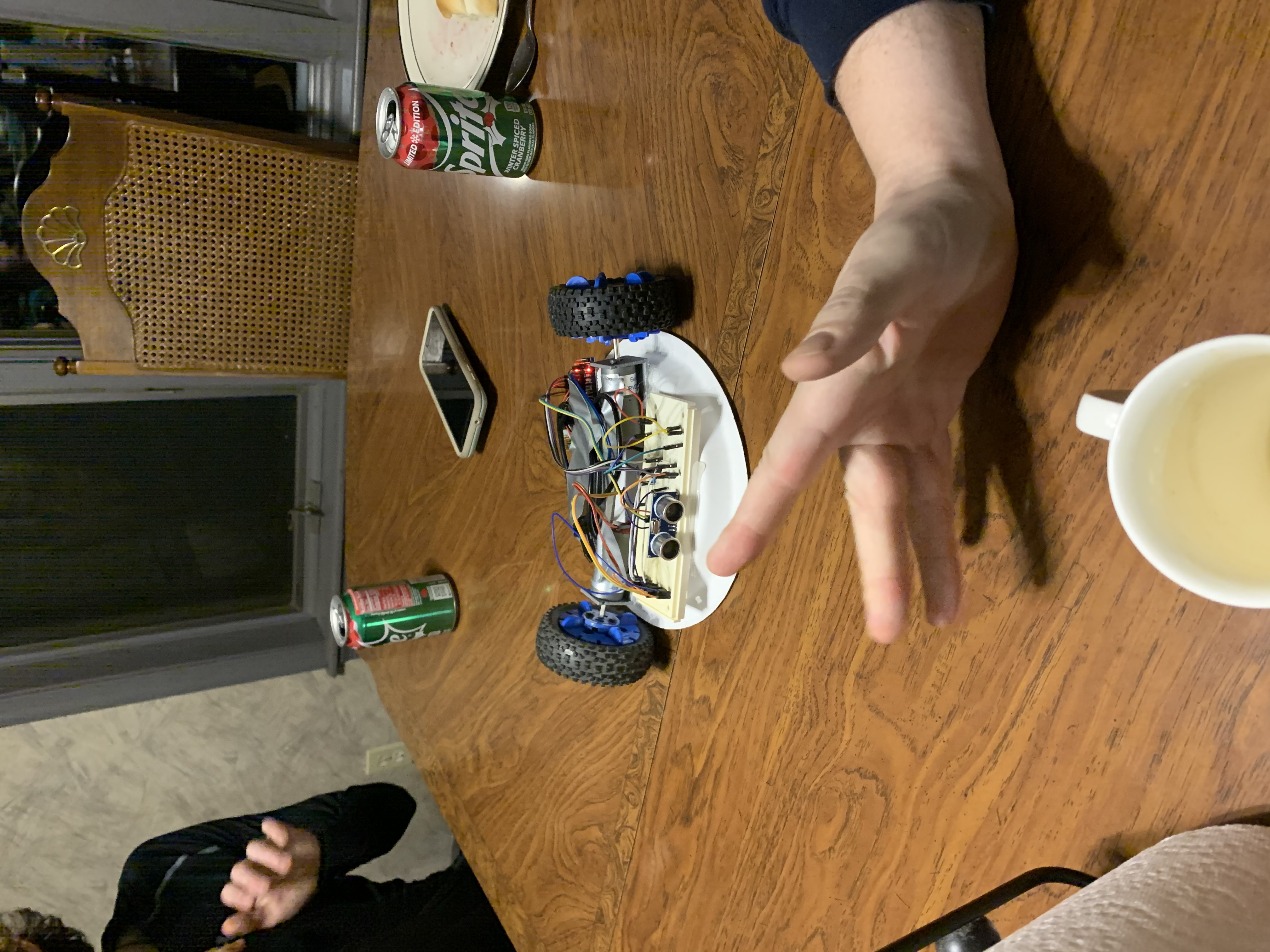
}And like that we have finished the code! Now onto the physical build. I started by designing a bracket for the motors I had, this bracket is up on my Thingiverse and in the GitHub repo for this project. I originally planned to screw these into a circle of wood (hence the holes for screws) but never ended up doing this and instead hot glued it to a paper plate. Next up I pulled out a breadboard and an Arduino nano. I wired pins 2 and 3 to the first motor, with a 1K ohm resistor on pin 2 so I could have a fast and high speed. I did this the same for pins 4 and 5 for the second motor. Then I placed pins 6 and 7 as the trigger and echo for the ultrasonic sensor. I finished up the electronics by using a spare 9 volt to 5 volt board I had to power the Arduino, and duck taping it all very nicely to the bottom of the plate. Here are some photos from the process:

Overall the robot was a ‘success’ in the sense that it was just as terrible as I expected it to be. The reaction from my family members was hilarious as I pulled the robot out and placed it on the table, seeing the confusion and impending doom as I turned it on and it inched forwards before dropping a piece of pie onto the table. It was also amazingly hilarious that the robot worked better upside down than the way it was originally designed to work in.
Thanks for reading and have a wonderful day!
~ Corbin